Upravit stránku

Assembly instructions FV THERM

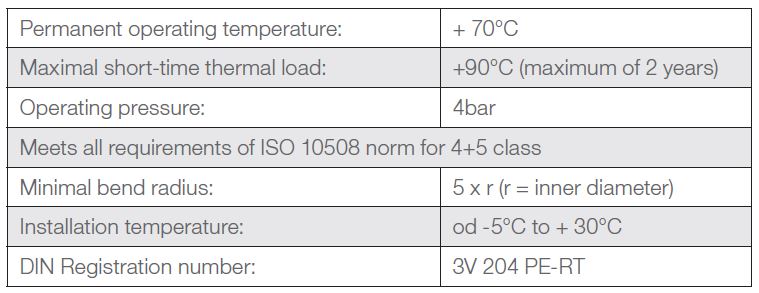
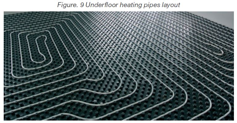
FV Therm underfloor heating system is designed for apartments, family houses, administrative and shopping centers and industrial buildings heating. The system is based on FV MULTIPERT-5 and FV MULTIPEX-5 quality pipes with EVOH oxygen barrier specially designed for the underfloor heating, their usage is the most economic for this purpose. FV MULTIPERT-AL  with a  lengthwise welded aluminium layer quality pipes can be used as well.

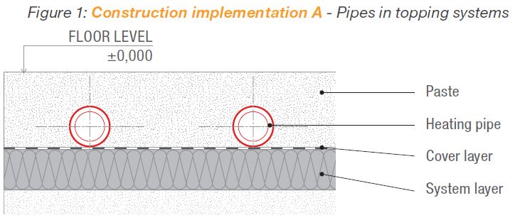
The FV THERM underfloor heating system is classified as a system for flooring in wet conditions in a construction implementation A group as per DIN 18560-2 on the basis of the arrangement of FV MULTIPEX-5 and FV MULTIPERT-5 heating pipes on an insulation layer.

1. FIELDS AND DILATATION JOINT SIZES

A topping is realized as per DIN 18560-1. Topping additives can be used for a better cement toppings processing. The size of topping sand grains should be between 0 – 8 mm. Topping fields of 1:1 or 1:2 joints ratio should not exceed 40 m2. See figure 3 for a dilatation fields and joints arrangement. Regarding the areas smaller than 40m2, the dilatation joints should be used if the side size exceeds 8m or the sticking out construction parts (corners, pillars, chimneys) limit the shape of a topping sheet.

The dilatation joints can be crossed using only connecting line in one level via a minimum of 200mm long protecting pipe for each joint side. Three measure points are required for each topping area of 200m2 to measure residual moisture. Heating circuit designing must have the size and shape of the topping sheet (see figure 3). Regarding the anhydrite poured toppings, the joint arrangement has to be consulted with a topping producer. The construction joints and the joints in the topping (motion joints) and in the final flooring have to be done. The topping is separated from vertical construction parts by the joints (marginal joints). If the contraction joints are in the heating toppings, they can be notched to one third of topping size maximum. A joint plan about the joints arrangement has to be made to inform about the type and arrangement of joints. The plan is made by a construction draftsman and presented as a part of realizing company performance descriptions.


The dilatation joints are made in accordance with the joint plan. A construction dilatation joint is made without any cut also in the place of underfloor heating if
there is one already. If the hard flooring is used, it is necessary to add the dilatation joint to this layer (see figure 5).

Protect the heating pipe when crossing danger zones (dilatation joints, door crossings, wall passages) by placing it into a FV PE protecting tube.

Only the intake and returnable pipes leading to individual circuits placed in sleeve can be put over the dilatation joint, not the circuit pipes. The minimum length of p ipe sleeve (see figure 8) is 20cm on each dilatation joint side. The minimum width of the dilatation joint is 8mm.

2. 2. UNDERFLOOR HEATING PIPES

FV MULTIPERT-5 and FV MULTIPEX-5 pipes belong to high-quality, controlled and certified products. After receiving plastic pipes on a construction site, transport, store and process them so that:

  • they are protected against any damage
  • heating pipes are not under direct sunlight
  • storage period does not exceed 3 months during unprotected storage
  • they are stored on a flat base without any sharp edges
  • they are protected against oils, fats, colors and longer effect of sunlight

The 5-layer highly flexible PE-RT system pipe has enhanced thermal resistance as per EN ISO 22391, with the oxygen barrier as per DIN 4726, with enhanced protection against mechanical damage during transport and handling on the construction site. Package contains 200m in taped bundle in cartons. Package weight is approximately 25 kg.

The permeability of oxygen at 40°C is deep under DIN 4726 limit. Using the HP method, the EVOH barrier layer is inseparably connected to the PE-Xa basic pipe with enhanced thermal resistance, highly flexible, from a webbed polyethylene.

Polyethylene heating pipes FV MULTIPERT-5

2.1. UNDERFLOOR HEATING ASSEMPLY STEPS IN FV THERM SYSTEM

Electric and sanitary installations, inner plasters and windows need to be finishedbefore the installation of insulations and square heating. Plasters need to be plast ered closely to the supportive base. An expert has to check the flatness of a row floor using a meter score before the installation of the underfloor heating system. Maximal altitude tolerance is 1cm on the entire installation room area. The meter scores are usually marked by a circle or other way at door spreads during the construction. Size tolerances are met as per DIN 18202 (ground constructions tolerance). The flatness needs to be checked before installing the insulation. Possible unevenness needs to be removed or flatten. The remaining plaster and other dirt need to be removed from the floor.

Ground bordering floor areas need to be insulated against moisture as per DIN 18195 (construction insulation). Accurate construction insulation execution definition is made by a draftsman or architect. A craftsman doing the insulation layout has to check sealing suitability and communicate in writing possible concerns about hydro insulation to construction administration. If a bitumen sealing assembly is done, of e.g. bitumen belts, it is necessary to lay a 0.1mm thick polyethylene innerlayer before the insulation layout. A foil is laid freely on the sealing. The pipes on the floor need to be properly fastened and secured against movement. The equalizing insulation needs to be laid to reach the floor proper structure. Another insulation layer can be put on the lower insulation. Only the “hard” insulation (EPS-DEO, PUR, …) can be used for the equalizing insulation. The multi-layer insulation individual layers joints cannot overlap but alternate (see figure 11).

3.1. FV THERM MARGINAL INSULATION BELT ASSEMBLY

The marginal insulation belt needs to be properly done on every vertical construction part such as pill ars, door openings, fireplace, elevator shaft and so forth. The marginal belt can be installed before laying the last insulation layer regarding the multi-layer construction thermal insulation. The marginal belt attached foil needs to be put so that the marginal joint between thermal and impact sound insulation is perfectly covered and the topping or water will not get into it. The marginal joints need to reach from the supporting base to the flooring surface and enable the minimal movement of 5mm regarding the heating toppings. The marginal belt has to be secured against movement when installing the topping. The insulation marginal belt situated above the topping sheet after being poured over can be removed only after top floor layer final laying to prevent the formation of an acoustic bridge or construction damage. Also, the pointing has to be finished before removing the rest of the insulation marginal belt. Afterwards, floor socle slats are fitted.

3.2. FV THERM system sheets layout

The system sheets choice depend on the thermal and impact sound insulation requirements as per ENEV / DIN 4109 / DIN 4108 norms. The insulation layers and system sheets layout is on the flat supporting base. If installation or electric lines are put on the raw floor, they need to be preserved and a space for them has to be created under the underfloor heating insulation. The multi-layer insulation first layer needs to be adjusted so that the whole-area base and current closed area are formed for the EPS system roll / the system sheets. Regarding the two-layer layout, the layers assembly has to be done with surpassing joints. The multi-layer sandwich foil on the upper side of system rolls / sheets is the insulation layer cover layer as per DIN 18560. A unilateral foil overlap serves as the expansion joints covering. The front expansion joints needs to be glued with a FV tape only. Filling parts inserted without the foil overlap need to be taped. It is necessary to tape properly before using the poured topping to prevent the topping or water getting into it. The dilatation joint needs to be preserved on the buildings. The floor maximal allowed assembly height has to be

3.3. Underfloor heating distributor cabinet fitting

Floor circuit distributors are fitted into cabinets. Beside the distributor, there are closing globe valves and system inflating and air bleeding valves in the cabinet. There are also regulation components or a pump or blending. The cabinet is fitted before the circuit assembly. The FV cabinet can be placed under the plaster if the wall is thick enough; if the wall is not thick enough, the FV cabinet is fitted on the wall.

3.4. FV THERM heating pipes layout

The pipes layout starts with heating pipes fastening on the intake distributor. When tightening screws (size 30), it is important to hold a counterpart (size 24) on the distributor. Tightening moment is limited to 30N. The pipes edges have to be separated under right angle. The floor to wall crossing place is protected by putting the pipe into FV click guide piece enabling to fix the curve ranging between 0 – 90°C. Attaching the pipes to FV EPS system roll area is done using a FV tacker clips and an original FV system stable gun. FV tacker clips are placed in the spacing of approximately 50 cm if the heating pipes are straight, the spacing of approximately 30 cm is used when changing direction. Alternatively, it is possible to put the fastening slats on the insulation and the pipes put into them.

Keeping the following spacing is needed for layout

  • Vertical construction parts: 50 mm
  • Elevators, shafts, chimneys, fireplaces: 200 mm

The 5 x r minimal bent ratio (pipes inner diameter) cannot be reduced as per DIN 4726 norm. The heating pipes layout can be serpentine or counter flow. Regarding the even heat dispersion, the serpentine layout is preferred as it creates a constant course of floor temperatures. Pipes with smaller spacing than in a living part are laid in the cooler places (the northern wall with a large window or the glass wall) and the marginal zone which is either a part of the circuit or a part of the separate circuit is created.

Regarding the turning loops layout in the middle of the heating circuit, it is necessary to keep the minimal size corresponding with bent ratios as per DIN 4726. The minimal bent ratio is 75mm for 15x1.8mm pipe, 85mm for 17x2.0mm pipe. See figure 14 in case of sharp bent, r=17x5=85mm, loop length 197 mm, width 170 mm valid for 17x2.0 pipe.

Sharp bent places formed after the violation of pipe’s minimal ratio have to be removed. The clips can be assembled only on the straight lines of the pipes. The marginal pipe is put approximately 5 cm away from the marginal belt on the PE foil forming the part the marginal belt. Fastening the first pipe to the base ensures that grout will not leak under the foil.

The FV clip should be placed on the straight lines of the pipes not in the bent in case of the heating pipe repair or the processing of remaining lengths. The pipe clip has to be measured and marked in the construction documentation.

FLOOR SURFACE TEMPERATURES

Deciding factor for the maximal surface temperature stipulation is the usage of a room. The maximal floor surface temperature is restricted to 29°C in the living area (wet rooms 33°C / the marginal zone 35°C) as per DIN EN 1264. The chosen flooring decides the surface temperature or the even distribution of the underfloor heating surface temperature.

The even distribution of temperature is decided by its heat permeability resistance, heating means excessive temperature, heating pipes layout spacing and
layout type.

FV THERM SYSTEM UNDERFLOOR HEATING FLOOR STRUCTURE

4. FV THERM FLOOR HEATING DISTRIBUTOR

Regarding the regulation technical possibilities, the separate heating circuit should be added to each room. The room is divided into several heating circuits if the room is larger than one circuit can cover. The circuits larger than 120 m are not allowed. Multiple heating circuits can form one dilatation unit.

Needed heating circuits distributor emerge from the number of installed heating circuits. Recommended maximum system pressure lost (including the distributor and connecting screws) is 250 mbar.

The distributor is designed so that it can be installed on the wall or the distributor cabinet. The maximal circuits number connected to one distributor is 12.

5. TIGHTNESS CONTROL

The device needs to be filled professionally and water-resistance checked after finishing installation. Norm VDI 2035 has to be met (the damage prevention in heating systems with hot water).

All intake and reverse valves are connected to the heating circuit distributor. A hose is connected to the water source. A hose ending in an outlet or outside the house is connected to a reverse arm. After the intake valve is opened, supply distributor is air bled. Afterwards, the first supply intake valve and the first reverse arm is opened.

When the heating circuit is filled with water so that no air is coming out of it, the first heating circuit is closed. The steps are analogous for other heating circuits. Filling and outlet armatures are closed when the filling and air bled process is completed. All intake and reverse valves are opened afterwards. The water-filled system undergoes a pressure testing as per CSN EN 1264 norm requirements. The pressure testing is done by water because of the pipes damage prevention. The testing pressure is twice the amount of the operating pressure but minimal of 6 bar (as per CSN EN 1264-4). The testing pressure is restored after two hours. Possible pressure decrease happens due to the pipes dilatation. The testing takes 12 hours. The pressure testing is successful if no water leaks from the pipes, joints and connection and the testing pressure does not decrease more than 0.1 bar per hour. A report about the pressure testing is made and inserted to the construction documentation.

The connecting system globe faucets are closed during the pressure testing to protect the heating devices and safety devices.

6. HYDRAULIC SETTING

Individual heating circuits setting is done when the tightening control is finished and before putting the device into operation (as per DIN EN 1264/EnEV). Individual heating circuits setting figures are stated in the project materials and set then on the supply arm flow indicators.

7. PASTE PRODUCTION AND PUTTING UNDERFLOOR HEATING INTO OPERATION

Pouring the underfloor heating pipes is realized after successful pressure testing is done. The pouring is done using the water-filled pipes and the operating pressure. Paste production meets DIN 1055 requirements.

Cement topping

FV plastificator is added to the cement topping for a better pipe covering, leaking concrete around the entire pipe, better heat permeability and against damages
formed because of the effect of air bleeding additives containing calcium or softeners added to the topping. The calcic sulphate and cement toppings are heated before the flooring layout. Function heating can be carried out no sooner than 21 days after using the cement toppings and 7 days using the calcic sulphate toppings.

Cement topping plastificator dosage:
MS = 6,0 · Ap · th. [kg]

where: Ap = underfloor heating floor area [m2]

th. = planned paste thickness [cm]

Ms = amount of FV plastificator for concrete [kg]

The theoretical usage of FV plastificator using 45mm thick sheet over the pipe:

  • For 1m2 of concrete topping = 0,39kg
  • For 1m3 of concrete topping = 6,0kg

This website uses cookies

This website is using cookies to provide services, personalize ads, and monitor traffic. By continuing to use this site you are agreeing with usage of cookies. More information.

Settings

Your privacy is important. You can choose from the cookie settings below. More information.