Upravit stránku

Assembly instructions FV INFRA

FV HDPE 100 and HDPE 100 RC pipes (resistant to cut) are used mainly for infrastructural water distribution. They are made from high-density polyethylene (HDPE, PEHD or I-PE).

HDPE 100 MRS firmness is 10 MPa – 2.5 times higher than up to now common used low-density polyethylene (LDPE). The wall thickness and hydraulic parameters of the stated pressure decreased considerably. HDPE 100 is more resistant to damage and chemicals and has better characteristics.

HDPE 100 RC pipes are more resistant to cut and damage by point load and are suitable for extreme conditions layout.

FV HDPE PIPING USE

FV HDPE 100 and FV HDPE 100 RC pressure pipes can be used for:

  • the distribution of drinking and non-potable water
  • the distribution of common cooling and non-freezing mixtures
  • the distribution of some water suspension
  • the distribution of some chemicals
  • the distribution of air and other gases
  • the hydro distribution of abrasive materials
  • primary circuits and thermal pump exchangers
  • snowmaking devices (snow cannons)
  • the construction of pressure and vacuum canalization systems

Liquid and loose materials can be distributed if the risk of electrostatic charge is not imminent. HDPE piping is resistant to the common chemicals, the distribution of drinking water from organic matter highly contaminated soil is not recommended.

LAYOUT

CSN EN 805 requirements regarding construction, lines and safety belt spacing need to be followed when placing the layout.

The drinking water distribution pipes are placed into non-frozen depth as per CSN 73 6005:

  • On the sidewalk and free terrain outside built-up area between 1.00 - 1.60 m (regarding the type and character of soil).
  • On the road minimum of 1.5 m.

Taking measures against water piping freezing using an insulation or heating is required in case of shallow mounting.

CSN EN 805 requirements regarding construction, lines and safety belt spacing need to be followed when placing the layout. The drinking water distribution pipes are placed into non-frozen depth as per CSN 73 6005:

  • On the sidewalk and free terrain outside built-up area between 1.00 - 1.60 m (regarding the type and character of soil).
  • On the road minimum of 1.5 m.

Taking measures against water piping freezing using an insulation or heating is required in case of shallow mounting.

TRENCH MINIMAL WIDTH AS PER PIPING DIAMETER:

TRENCH MINIMAL WIDTH AS PER TRENCH DEPTH:

d – pipe outer diameter [mm], D – pipe outer diameter [m], β – non-supported trench wall angle. The lowest working spacing between pipe wall and (supported) trench wall is x / 2.

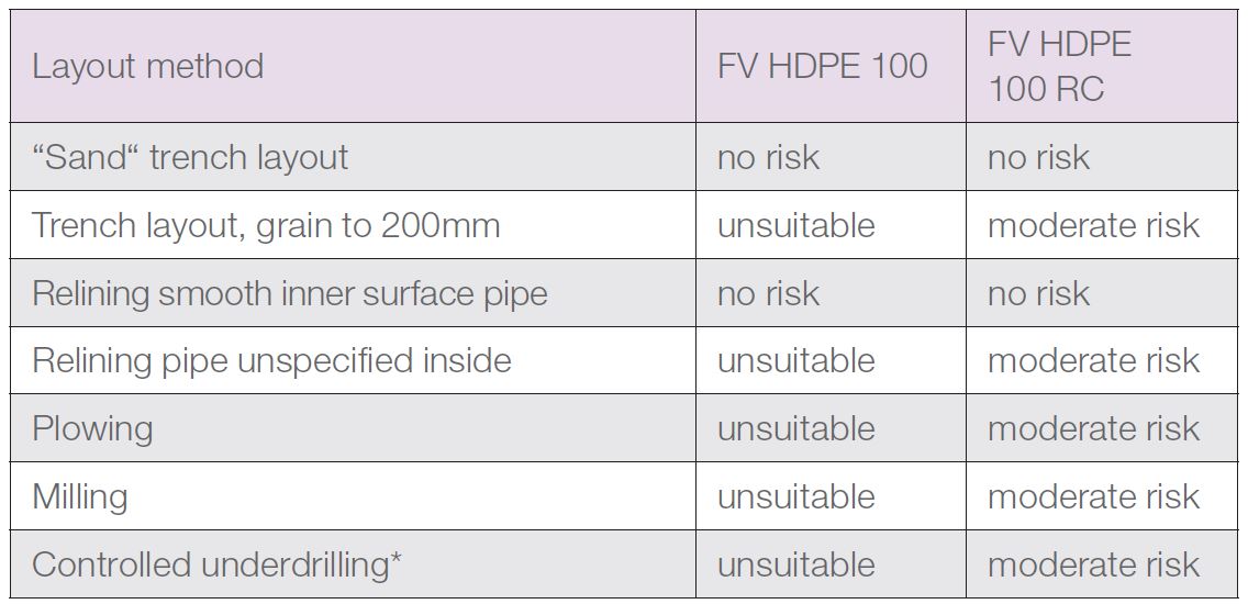
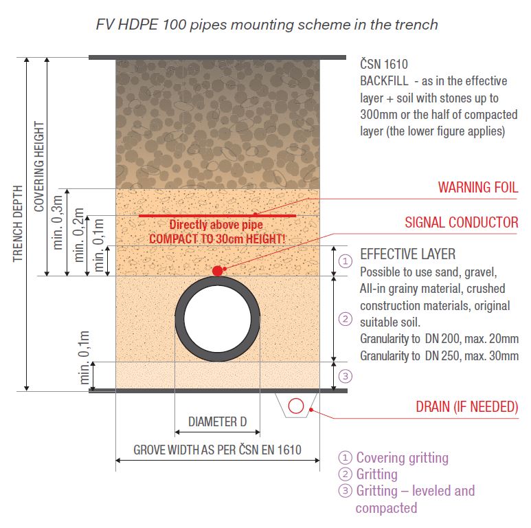
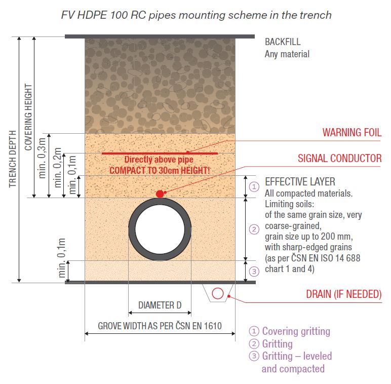
The soil under the pipe and to 15 cm above pipe upper margin is considered effective (see schematic sectional views of mounting).Embankment and compaction is made layer after layer, always on pipe’s both sides. The pipes of 110 mm diameter or higher are compacted manually or using soft-compacting machinery. Compaction is not used directly above the pipe to the height of 30 cm. When compacting, the pipes cannot be moved vertically or horizontally. PE 100RC pipes can be used for so called “non-sand layout” for most common trenches and covered by dig material to 50 % of aggregate additives of the size to 250 mm.

The PE100 pipes are placed into the trench on sand or sandy gravel base of minimal thickness of L = 10 cm. The soil does not need to be compacted, although it cannot be too loosen. The effective layer gritting is made by sand or soil without sharp-edged parts for the HDPE 100 piping and pipe fittings. The pipes cannot be placed on the frozen soil. The entire pipes have to lay on the terrain, without point contact with the rock - assembly holes are created in case of the mechanical pipe fittings or the electrofusion pipe fittings. Mounting angle should be larger than 90°. The new sand or sandy gravel base has to be created for the pipes (excluding
RC pipes) in rock or stone bedrock after removing approximately 15 cm layer. For pipe fittings gritting, the sand is used for each type of piping if not stated
differently. The gritting should exceed the pipe fitting by 20 cm minimum on each side.

The pipes CANNOT be placed directly on concrete or other hard surfaces. If the concrete sheets are used in soils of low-bearing capacity, the 15 cm sand or sandy gravel base has to be created.

PIPING GRITTING AND BACKFILL

The soil corresponding with the specification for the effective layer and given type of piping is used. Hollows cannot emerge in the pipe surroundings, thus, materials that can change their volume or consistency cannot be used for backfill. Water pipes cannot go through the soil contaminated by organic material. This soil cannot be used for gritting. The unsuitable soil has to be replaced with suitable soil.

A warning foil marking the pipes it recommended as per CSN 73 6006 (8/2003). The foil should be placed above the pipe top in 20 cm minimum. The material and compaction method corresponding to the use of given area is used for the pipes

WELDING

The HDPE pipes and pipe fittings can be blunt welded or welded by means of electrofusion fitting, occasionally polyfusion welded. The HDPE100 and HDPE 100 RC pipes and pipe fittings welding is not restricted.It is not possible to weld polyethylene and polypropylene. Also, it is not possible t o weld HDPE, lPE, PE80, PE100 and LDPE, rPE, PE40 polyethylene pipes or pipe fittings. HDPE and LDPE non-welded pipes can by connected by mechanical couplers only.

PIPES BENDING/ PIPING DIRECTION CHANGES

The corresponding pipe fittings are used to change the direction. Shaping the pipes on a construction site using heat is not allowed. HDPE flexibility enables
the changing the direction or copying the terrain by making bents in the ratio R. The bent ratio depends on the diameter of the pipe and on temperature, it does not depend on pipe’s pressure class.

ALLOWED BENT RATIOS

The usage of pipe fittings and pipes can be lowered by suitable bent implementation when performing trench works.

DISTRIBUTION, STORAGE AND MANIPULATION

  • The entire pipes have to be placed on the base when distributed and stored. Underlaid beams should not be narrower than 50mm.
  • Pipes placed in rods cannot be bent on edges. Pipe endings exceeding the vehicle loading area by more than 1m need to be supported.
  • Pipes cannot be moved on sharp gravel or base.
  • Maximal pipes storage height is 1.6m, side support spacing should not exceed 3m.
  • Longer pipes storage under direct sunlight can lead to the change of color.
  • HDPE piping can be stored and manipulated with also in the winter (the temperature should not exceed – 20°C).
  • Products have to be protected against the contact with solvents and toxic materials contamination.
  • Pipes and pipe fittings safety covers can be removed closely to their use.
  • Folded pipes are stored vertically, secured against fall, or horizontally up to 1.6m height.
  • Before unpacking the pipes, remove the tape securing the outer pipe end and loosen gradually following layers. We recommend loosening only the amount of piping needed.
  • Unfolding device (cart) is recommended for unfolding the pipes, it is possible to use a slow-moving vehicle.
  • Unfolding the pipe in spiral is not allowed – pipe can break.
  • When unfolding or straightening, the pipes cannot be strained by excessive bending, especially when the temperature is low.
  • We recommend adding straightening devices to the unfolding cart.

ALLOWED PIPE DAMAGE WHEN USING FOR PRESSURE APPLICATIONS

The maximal pipe wall damage depth:
FV HDPE 100 - allowed gritting only: max. 10% of wall thickness
FV HDPE 100 RC - sand gritting: max. 15 % of wall thickness
FV HDPE 100 RC - different gritting: max. 10 %

This website uses cookies

This website is using cookies to provide services, personalize ads, and monitor traffic. By continuing to use this site you are agreeing with usage of cookies. More information.

Settings

Your privacy is important. You can choose from the cookie settings below. More information.